Industrial CNC Machining: How to Meet the Most Stringent Engineering Standards
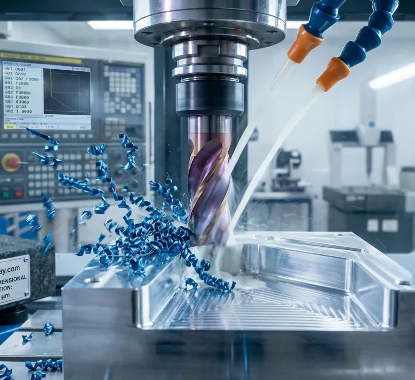
In the development of modern mechanical components, the difference between a working prototype and a catastrophic failure on the assembly line comes down to fractions of a millimeter. When a design moves from the CAD software screen to the production floor, engineers aren’t just looking for a part that «looks like» the digital model; they demand structural predictability, geometric consistency, and strict adherence to design specifications. The industrial CNC machining It has established itself as the gold standard for transforming metal alloys and engineering polymers into high-precision critical components, where there is simply no room for error.
The True Meaning of High Precision in Industrial Machining
For the general public or the local community maker, a tolerance of one-tenth of a millimeter may seem imperceptible. However, in highly demanding industries such as aerospace, automotive, robotics, or medical device development, that one-tenth of a millimeter represents an insurmountable gap.
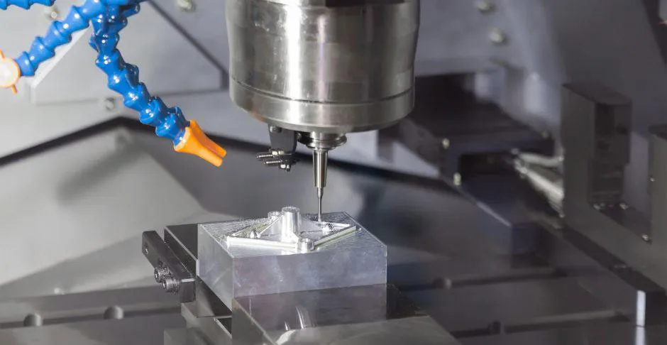
He high-precision CNC machining It is not limited to automated material cutting; it involves complete control over kinematic variables, the thermal stability of the machinery, the microscopic wear of cutting tools, and the rigidity of the clamping systems. When we talk about industrial standards, precision is measured based on repeatability: the ability to replicate exactly the same geometry in the first part and in the ten-thousandth part.
The fine line of tight tolerances (ISO 2768 and beyond)
The universal language of engineering drawings is dimensioning, and at the heart of this language is the assignment of tight tolerances. These restrictions specify the maximum allowable deviation from the nominal dimensions of a design.
At the international level, the standard ISO 2768 It is the reference framework that defines the general tolerances (divided into classes: fine, medium, coarse, and very coarse) for linear and angular dimensions without specific indications.
However, highly complex technical projects often exceed these general limits, requiring specific geometric and dimensional tolerances (GD&T) that reach critical ranges of up to $\pm0.01\text{ mm}$ or even microns in shaft diameters, bearing seats, and sealing channels.
A common mistake when designing for manufacturing is to ignore the cumulative impact of tolerances in a complex assembly. If three adjacent components are manufactured at the upper limit of their allowable tolerance, the final assembly will experience mechanical interference that will prevent it from functioning properly.
This is where design for manufacturability (DFM) and the selection of a manufacturing partner with rigorous dimensional inspection capabilities determine the success of the project.
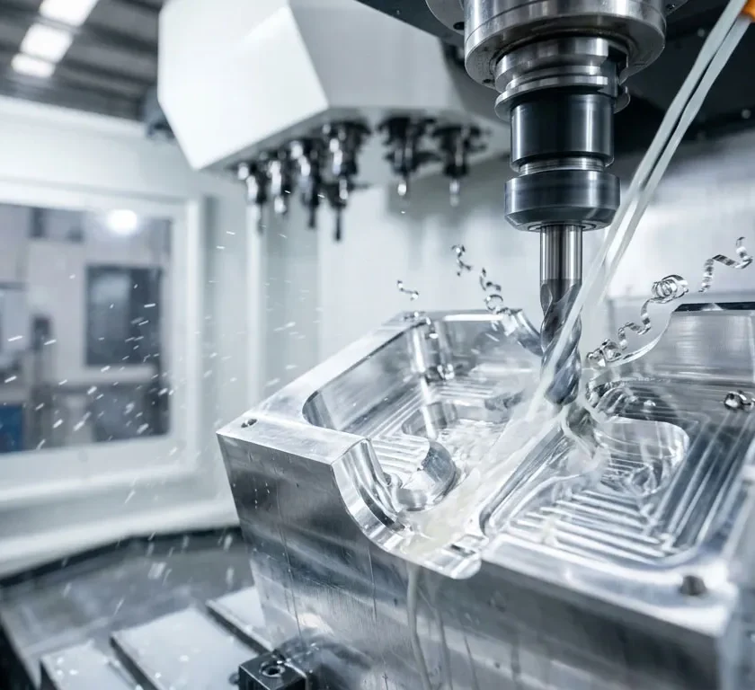
Surface finish: More than just aesthetics—a functional necessity
In the design of high-performance mechanical components, the surface finish It is not merely a cosmetic treatment. The microscopic texture left on the material by a cutting tool directly determines how that part will interact with its operating environment.
An excessively rough surface can accelerate frictional wear, destroy hydraulic seals in a matter of hours, or act as a stress concentrator, leading to premature fatigue failure under cyclic loads. Conversely, a controlled and specific finish can optimally retain lubricants, improve corrosion resistance, or ensure the uniform contact necessary for efficient heat transfer.
Understanding Ra, Rz, and Post-Processing
To quantify and describe the texture of a machined surface, engineers use standardized roughness parameters. The most commonly used ones in technical documentation are:
- $R_a$ (Arithmetic Mean Roughness): This is the most common global parameter. It represents the arithmetic mean of the deviations in profile height from its centerline over a sampling length.
- $R_z$ (Maximum Profile Height): It measures the vertical distance between the highest crest and the deepest trough within the evaluation length. This is crucial for identifying isolated but severe imperfections that the $R_a$ average might mask.
Upon completion of a process industrial CNC machining, the pieces are in a condition known as as-machined (as machined). Depending on the tool feed rate and the radius of the cutting insert, the standard machining depth typically ranges from $R_a$ to $3.2\,\mu\text{m}$ and $1.6\,\mu\text{m}$.
When project requirements are more stringent, advanced post-processing techniques are used to modify both the microgeometry and the chemical properties of the surface layer:
| Finishing Process | Typical Surface Roughness Range (Ra) | Main Application |
| Machine Standard (As-Machined) | $3.2 – 1.6\,\mu\text{m}$ | Structural components, housings, and frictionless parts. |
| Shot blasting (Bead Blasting) | Change texture (matte finish) | Removes tool marks, evens out the surface, and prepares the surface for painting. |
| Anodized (Type II / Type III Hardcoat) | Varies by base, alters microns | It dramatically increases wear and corrosion resistance in aluminum. |
| Mirror Polish / Grinding | $ < 0.2 μm $ | Seats for dynamic seals, injection molds, and optical components. |
Choosing the right surface finish requires a careful balance between the part’s function and manufacturing costs. Requiring an extremely low $R_a$ in non-functional areas only increases cycle times and unit cost without adding any real value to the final component.
Engineering-grade materials: The challenge of machinability
Material selection is the cornerstone of the mechanical integrity of any component. However, from the perspective of the industrial CNC machining, each material exhibits unique behavior under shear stress.
The machinability —the relative ease with which a material can be cut while maintaining a good finish and without premature tool wear—is a critical factor that affects both the cost and the lead time of a part. Engineering-grade materials require highly specific cutting parameters, high-pressure cooling, and advanced tool geometries to prevent thermal deformation or microcracks during the process.
From technical aluminum alloys to superalloys and engineering plastics

The range of materials used in high-precision machining is divided into three main categories, each with its own mechanical and thermal challenges:
1. Aluminum Alloys and Non-Ferrous Metals
They are the most popular due to their excellent strength-to-weight ratio and high machinability.
- 6061-T6 aluminum: The industry standard. It offers excellent weldability and corrosion resistance, making it ideal for structural components and mounting jigs.
- 7075-T6 aluminum (Ergal): When alloyed with zinc, its mechanical strength is comparable to that of many steels, making it the material of choice for aerospace and high-performance racing applications.
2. Steels, Stainless Steels, and Superalloys
Materials whose toughness and heat resistance make them difficult to machine.
- 316L Stainless Steel: Excellent resistance to marine and chemical corrosion. Its tendency to work hardening (work hardening) requires extremely sharp carbide tools and constant feed rates to prevent the workpiece from becoming uncutable.
- Grade 5 Titanium (Ti-6Al-4V): It has low thermal conductivity. This means that the heat generated by friction is not dissipated with the chip, but rather concentrated at the tool edge, requiring high-speed milling (HSM) strategies and internal cooling.
3. High-Performance Polymers
Engineering plastics that successfully replace metals in low-friction or electrical insulation applications.
- POM (Delrin / Acetal): It is known for its superior dimensional stability, low moisture absorption, and excellent machinability. It is the material of choice for precision gears, bushings, and sliding components.
- PEEK (polyetheretherketone): A semi-crystalline thermoplastic capable of withstanding continuous operating temperatures of up to 250°C. Its high rigidity requires cutting parameters similar to those used for soft metals to prevent burrs and ensure tight tolerances.
Do your parts require pinpoint precision? Discover JUSTWAY.com's industrial CNC machining service

Turning a technical design from CAD software into a physical component that meets micron-level tolerances and controlled surface roughness requires world-class infrastructure.
For engineering and industrial design departments, finding a supplier capable of reliably ensuring this consistency is often a logistical challenge.
This is where the on-demand manufacturing platform from JUSTWAY transforms the paradigm of critical component manufacturing.
With a fleet of state-of-the-art machinery, including CNC machining centers with up to 5 axes, JUSTWAY breaks down the traditional barriers of contract manufacturing through an optimized digital ecosystem:
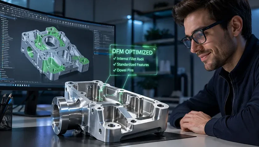
- Instant Quote with DFM Analysis: When you upload your CAD files in standard formats (such as STEP or IGES), the platform not only calculates the cost immediately but also performs an automatic design-for-manufacturing (DFM) analysis, identifying inaccessible internal corners or excessively thin walls before production begins.
- Rigorous Quality Control: Every order undergoes rigorous dimensional inspections using Coordinate Measuring Machines (CMMs) and optical projectors, ensuring compliance with ISO 2768 and the custom tolerances specified in your drawing.
- Material Traceability: From aerospace-grade aluminum to highly specialized polymers such as PEEK, JUSTWAY provides material certificates and inspection reports that confirm the final component will perform exactly as intended under the load and engineering conditions for which it was designed.

Whether you need a single working prototype or high-mix, low-volume production runs, outsourcing manufacturing to a technology partner allows you to focus your resources on what matters most: innovation and design.
Don't waste any time—the service your company deserves and needs is just a click away!
It's your turn to share your thoughts!
Strict adherence to tolerances and the right surface roughness are the key factors that distinguish a visual prototype from a functional engineering component. What has been the most complex machining challenge you’ve faced in your projects or designs?
Leave a comment below and share your experience with the community.
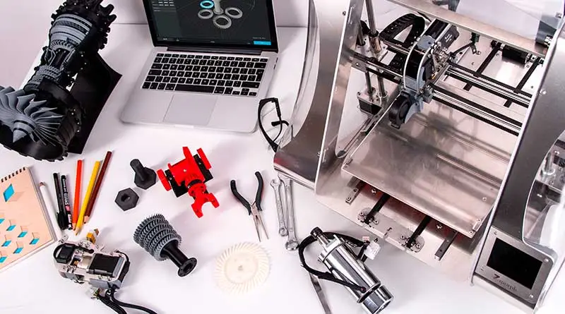
If you want to play an active role in the evolution of additive manufacturing and digital machining, network with other industry professionals, and gain access to exclusive features, Sign up on our website. Join the region's largest 3D printing and manufacturing community!

Responses