
Precision CNC Machining: A Guide to Choosing Geometric and Dimensional Tolerances Without Increasing Your Project Costs

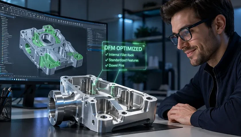
In mechanical design, there is an unwritten but ironclad axiom: Every additional micron of precision costs money. When designing a component to be manufactured using computer numerical control (CNC) machining, the temptation to apply ultra-tight tolerances to the entire CAD model to «ensure that everything fits perfectly» is a common mistake that can triple production costs without providing a single functional benefit.
CNC machining is one of the most versatile and precise manufacturing technologies in the world, capable of shaping solid blocks of metal or plastic with astonishing repeatability. However, demanding absolute precision in areas of the part that do not interact with any other component is the equivalent of paying for a jewelry-grade finish on the internal chassis of industrial equipment.
The True Art of the Design for Manufacturing (DFM) In CNC machining, the goal is not to produce the most precise part possible, but to identify where precision is critical and where standard commercial tolerances are more than sufficient.
In this guide, we’ll discuss how to balance dimensional and geometric tolerances (GD&T) in your technical drawings, avoiding unnecessary cost overruns and ensuring that your project maintains the highest structural quality at the lowest manufacturing cost.
Dimensional vs. Geometric Tolerances (GD&T): Understanding the Technical Difference
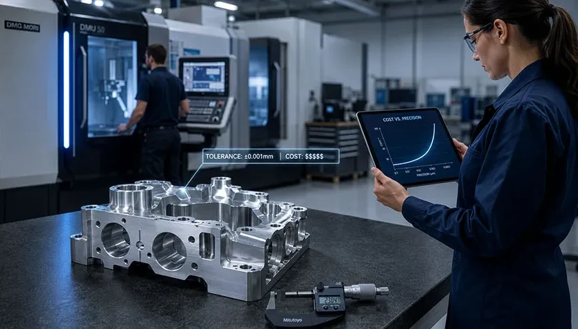
To master cost control in CNC machining, the first step is to avoid confusing the size of a feature with its shape or position. In modern technical drawing, these two concepts are divided into dimensional tolerances and geometric tolerances.
                  +-----------------------------------+
                  |  TOLERANCES IN CNC MACHINING    |
 +-----------------+-----------------+
                                    |
 +-----------------------+-----------------------+
 | |
 v v
+-----------------------+ +-----------------------+
|    DIMENSIONAL | |  GEOMETRIC (GD&T)   |
+-----------------------+ +-----------------------+
| • Magnitude / Size   | | • Shape / Orientation |
| • E.g.: Ø10 ±0.05 mm    | | • E.g.: Concentricity  |
| • Caliper / Micrometer | | • CMM / 3D Probing    |
+-----------------------+ +-----------------------+
Dimensional tolerances ($\pm\text{mm}$)
Dimensional tolerances define the acceptable limits of the physical quantity of a feature. They tell the machine how much the width, length, depth, or diameter of a part can vary from the nominal value.
- Example: A shaft with a diameter of $\text{Ø}10 \pm 0.05\text{ mm}$ means that any part with a diameter between $9.95\text{ mm}$ and $10.05\text{ mm}$ will be accepted.
- Inspection: It's quick and inexpensive; all you need to do is use vernier calipers or manual micrometers directly at the machine.
Geometric Tolerances (GD&T)
Geometric Dimensioning and Tolerancing (GD&T) goes one step further: it controls the spatial relationship and form of the features. A part may have the correct dimensions but still not function properly if it is bent, tapered, or off-center.
GD&T governs aspects such as:
- Format: Flatness, cylindricity, straightness.
- Guidance: Perpendicularity, parallelism, angularity.
- Position and Concentricity: The exact location of the center of a hole relative to a reference system (datum).
The impact on costs: While verifying a dimensional tolerance takes only a few seconds with a micrometer, validating a strict positional or flatness tolerance requires mounting the part on a Coordinate Measuring Machine (CMM). This process requires advance programming, a temperature-controlled environment, and a specialized operator, which substantially increases the unit cost.
Standard tolerances (±0.1 mm) vs. tight tolerances (±0.01 mm or less)
To avoid cost overruns, it is vital to understand what happens in the workshop when we move from standard commercial specifications to high precision.
| Parameter | Standard Tolerance (±0.1 mm) | Tight Tolerance (±0.01 mm) |
| A Threat to the Budget | Bass (Usual trading limit) | Winger (Increase the cost by $200\%$–$400\%$) |
| Tools | Standard carbide end mills. | Specialized tools, diamond-tipped or ground. |
| CNC Machining | 1 or 2 passes (roughing and finishing). | Multiple ultra-slow finishing passes. |
| Environmental Control | Workshop ambient temperature. | Climate-controlled metrology room ($20^\circ\text{C}$). |
| Scrap rate | Minimum ($ < 1\%$). | High, due to minimal vibration or tool wear. |
The impact on the production line
By specifying $\pm0.01\text{ mm}$ (or less), you force the machinist to reduce the milling machine’s feed rates to avoid causing tool deflection or transferring excessive heat to the metal block, since Thermal expansion of the material would affect the measurement. In addition, natural wear on the cutter's cutting edge will require constant recalibration halfway through the batch.
How Excessive Precision Exponentially Increases Production Costs
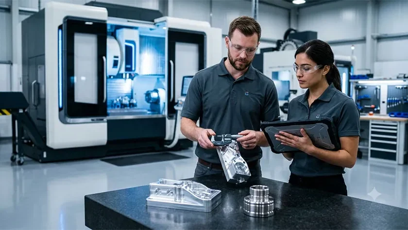
There is a strongly nonlinear relationship between the required accuracy and the final cost of the project. Halving a tolerance does not double the cost: in many cases, triples or quadruples it. This happens because tightening the tolerances forces the machine shop to abandon standard machining routines and adopt highly complex protocols.
       Cost
 ^
 | / (High Precision / CMM)
 | /
 | /
 | /
 | _---- (SURCHARGE ZONE)
 | _--
        | _--
 | _----
 | _----  (DFM-OPTIMIZED ZONE)
        +--------------------------------------------------------> Tight Tolerance
        Looser (±0.2 mm)     Standard (±0.1 mm)    Strict (±0.01 mm)
1. Premature wear and high-end cutting tools
To achieve high-precision finishes and keep deviations below $0.01\text{ mm}$, conventional carbide end mills are not sufficient.
- The workshop must use tools with special coatings or polycrystalline diamond (PCD) inserts.
- Tool wear becomes a critical factor: even invisible wear of just a few microns on the cutting edge will cause the workpiece to fall outside specifications, forcing tools to be replaced much more frequently.
2. A sharp increase in the rejection rate (Scrap Rate)
When tolerances are wide, most parts turn out right the first time. But when working within micrometer margins, small unforeseen issues such as:
- A slight variation in the hardness of the raw material block,
- A microscopic metal shaving trapped in the clamping jaw, or
- A current fluctuation in the machine's spindle,
…will result in the item being discarded immediately. The workshop inevitably passes on the financial risk associated with that wasted material to the final price of your order.
3. Long cycle times and bottlenecks
To prevent the metal from overheating and to avoid generating cutting forces that cause the tool to bend, the operator must configure the CNC machine with feed rates (feed rate) extremely slow and apply multiple finishing coats.
A part that could be machined in 8 minutes with standard tolerances may end up requiring 35 minutes just to ensure that its diameter or flatness is flawless. In CNC machining, machine time is the main cost component.
4. The Hidden Metric: Quality Inspection
The work isn't over when the machine stops. If the drawing specifies critical tolerances, the part cannot leave the shop without being validated.
The cost of measuring: A visual inspection or one using a caliper takes just seconds. Inspecting tight tolerances requires thermally stabilizing the part in a metrology room and using a CMM (Coordinate Measuring Machine). This quality control process can cost more than the actual machining of the metal block.
DFM Strategies for Optimizing Tolerances Without Sacrificing Functionality
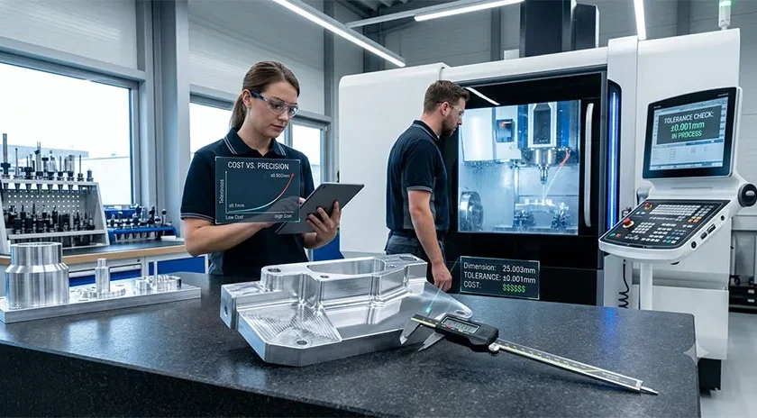
The secret to Design for Manufacturing (DFM) is not to compromise the part's performance, but rather Bringing precision to where it really matters. By making small geometric changes to the CAD model, it is possible to drastically reduce machining time without altering the component's function.
1. Avoid sharp inside corners and make the fillets deeper
CNC cutting tools (milling cutters) are cylindrical and rotate around their own axis. By their very nature, A milling cutter cannot cut a perfect internal angle of $90^\circ$.
- A common mistake: Designing a rectangular housing with sharp corners forces the workshop to use electrical discharge machining (EDM) or to attempt finishes using tiny milling cutters and very tight tolerances.
- The DFM solution: Add a radius to the inside corner that is at least $10\%$ or $15\%$ larger than the radius of the tool you plan to use. Better yet, if the corner needs to fit into a square part, design a relief or «dogbone» (dogbone/undersize relief).
       NOT RECOMMENDED RECOMMENDED (DFM)
    (Requires EDM or fine milling cutters) (Use of radio / Dogbone)

      +---------------+ +---------------+
      | | | |
 | | | |
 | | | |
 +---------------+ (---)+-----+(---)
      | Live Corner  | |     |
 |   (90 deg)    | +-----+
2. Blind Holes, Threads, and the Diameter Rule
Trying to maintain tight tolerances at the bottom of a deep cavity or along a long thread is a surefire way to make the part more expensive.
- Cavity depth: Keep depths below 4 times the diameter of the tool ($4 × D$). Beyond this limit, the milling cutter bends, vibrates, and loses its dimensional accuracy.
- Functional threads: A thread depth greater than $2$ or $2.5$ times the screw diameter ($2 × D$) is rarely required. Beyond that length, the first few threads bear almost the entire load; extending the thread with tight tolerances only increases the risk of the tap breaking.
3. Guided by dowel pins rather than general tolerances
If two aluminum plates must be aligned with millimeter precision during assembly, a common mistake is to apply a tolerance of $\pm0.02\text{ mm}$ to the entire perimeter or to the holes for the fastening screws.
- The DFM alternative: Machine the part's outline and the screw holes to a generous standard tolerance ($\pm0.1\text{ mm}$).
- The trick: Include only two holes for locating pins or dowel pins reamed to the exact required tolerance. In this way, the accuracy of the assembly is ensured by the pins, while the remaining $95\%$ of the part is machined at high speed and low cost.
4. Focus on the accuracy of individual features (Features)
Do not treat the entire surface as if it were a single critical entity. Use 2D planes to restrict strict tolerances to only the functional faces.
- Available spaces: Standard commercial tolerance ($ ± 0.1 mm $ to $ ± 0.2 mm $).
- Bearings: Maintain the housing with the specified tolerance (for example, ISO H7 / $ ±0.015 mm $), but limited exclusively to the bearing seating area.
Do your CNC parts require strict tolerances without breaking the budget? Get a quote in seconds with Justway.com

Designing the perfect part is only half the job; the other half is finding a manufacturing partner who understands the fine line between the required precision and cost control. In Justway.com, turning your CAD models into high-quality physical components no longer requires weeks of negotiations or opaque quotes.
As a global on-demand manufacturing service, Justway combines state-of-the-art CNC machining technology with a smart digital platform designed to optimize every stage of your production.
Custom CNC Machining: From the Initial Idea to Mass Production
Justway’s CNC machining service is designed to meet the technical requirements of industrial, automotive, aerospace, and consumer electronics projects. Whether you need 3-, 4-, or 5-axis milling, or high-precision turning, the platform lets you choose from a wide variety of metals (aluminum, stainless steel, titanium, brass) and engineering plastics (POM, PEEK, Nylon, PTFE).
- Automated DFM analysis: When you upload your CAD file, the platform not only calculates the cost but also analyzes the geometry to detect potential tolerance issues or inaccessible corners before cutting the first block of material.
- Rigorous quality inspection: Each batch undergoes strict metrological inspections (including CMM reports if your project requires them) to ensure that the geometric and dimensional tolerances specified in your drawing are strictly adhered to.
Rapid Prototyping with Justway: Validate Your Design Before Scaling Up
Before committing to a mass production run, it is crucial to validate the fit, form, and function of your component to avoid costly errors. The service Justway's Rapid Prototyping It is designed specifically to speed up your product development cycle without draining your resources.
Key benefits of rapid prototyping at Justway:
- Instant online quote: Upload your 3D model and get a transparent breakdown of costs in a matter of seconds, eliminating the need to wait days for a manual quote.
- Ultra-fast delivery times: With distributed production capabilities and automated processes, you can have your functional prototypes delivered right to your workshop or office in just a few days.
- Agile and cost-effective iteration: Evaluate different options for materials, tolerances, or surface finishes on individual units before moving on to mass production.
- No minimum order quantity (MOQ): From a single prototype to validate an assembly to short production runs, Justway offers you complete flexibility without requiring minimum order quantities.
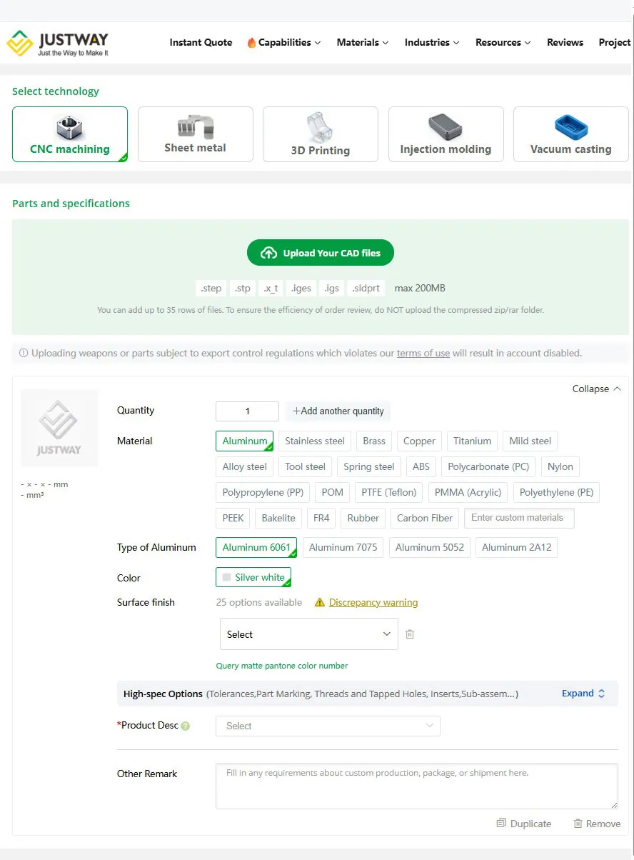
If you're looking to take your designs to the next level with the perfect balance of precision, speed, and cost, Visit Justway.com and upload your CAD file today to experience the new era of digital manufacturing.
Conclusion and Checklist for Verifying Your CAD File/Drawing Before Submission
Adjusting tolerances does not mean compromising the quality of your product, but rather Design with financial and functional intelligence. By limiting high precision exclusively to the mechanical areas where it is essential, you optimize machine time, drastically reduce scrap rates, and ensure that your project’s cost stays within budget.
Before exporting your CAD model or submitting your technical drawings for a quote, use this quick checklist:
DFM Checklist for Tolerances in CNC Machining
- [ ] Does the standard tolerance apply in non-critical areas?Make sure that the general tolerance box in your drawing specifies the commercial standard (such as $\pm0.1\text{ mm}$ or ISO 2768-m) for all dimensions that do not interact with other parts.
- [ ] Do the inside corners take the tool radius into account?Verify that the rectangular cavities have corner radii slightly larger than the radius of the standard end mill or include geometric reliefs (dogbones).
- [ ] Are you using location pins (dowel pins) for lineups?Instead of requiring tight tolerances on all mounting holes or edges, it focuses precision on just two reference points.
- [ ] Is the depth of the cavities proportional to their diameter?Ensure that the cutting depths do not exceed the ratio $4 × D$ to prevent vibration and deflection of the cutting tools.
- [ ] Are geometric tolerances (GD&T) absolutely necessary?Determine whether flatness, concentricity, or perpendicularity checks will require the use of a CMM and whether they actually add value to the part's function.
Applying these criteria during the design phase makes the difference between a prototype that is unfeasible due to cost and a component that is ready to be scaled up into production quickly and cost-effectively.
Your turn! How do you manage tolerances in your projects?
Striking a balance between precision and budget is one of the most exciting challenges in industrial design. Every workshop and every designer has their own «golden rules» when preparing a file for CNC machining.
- Have you ever had an experience where overly strict tolerances caused your project costs to skyrocket?
- Which DFM strategy has worked best for you in optimizing your CAD models?
Leave us a comment below and join the conversation. In 3dprinting.website We love sharing ideas and manufacturing tips with our community. And if you found this guide helpful, share it with your team or on social media so that more engineers and creators can optimize their designs and reduce their manufacturing costs!
Responses