
Design Guide for Industrial 3D Printing: How to Optimize Parts and Reduce Manufacturing Costs

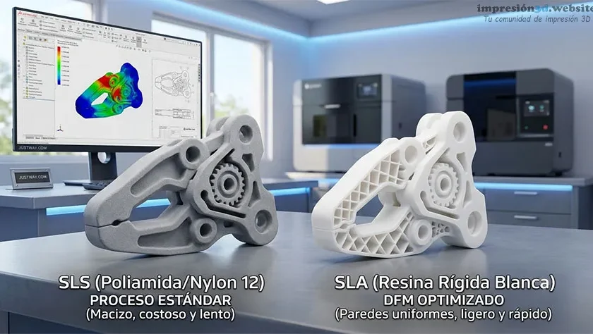
With home 3D printers, a design error usually results in a few hours of lost time and a couple of grams of filament. However, when sending a CAD file to on-demand manufacturing platforms, every cubic millimeter of unnecessary material, every poorly planned support structure, and every complex geometry directly translates into an increase in the final cost.
This is where the DFM (Design for Manufacturing) or Design for Manufacturing.
Applying DFM to industrial additive manufacturing means understanding how professional-grade technologies (such as SLS or SLA) work in order to adapt our digital models before submitting them for a quote. The goal is not only to ensure that the part is functional, but also to design it so that its production is as fast, clean, and cost-effective as possible.
Optimizing your CAD files for an industrial environment doesn't mean sacrificing the performance of your components. On the contrary: making a few strategic adjustments to wall thicknesses, orientations, and tolerances will allow you to take full advantage of the precision of industrial machines, drastically reducing manufacturing costs without compromising the quality of your prototypes or final products in any way.
1. Wall Thicknesses and Basic Geometry: The Balance Between Strength and Material
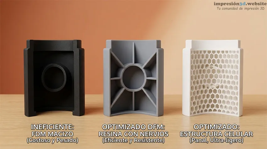
One of the factors that most influences the final price of an industrial part is the total volume of material used and the time it takes for the machine to process it. Finding the right balance between structural rigidity and material savings is the first step toward mastering efficient design.
The Impact of Wall Thickness on Cost
In traditional injection molding, thick walls cause sink marks and warping. In industrial 3D printing, the problem is purely economic and time-related. Excessively solid sections increase the volume of material used and force lasers or energy sources to make more passes per layer. This slows down production and increases the cost of the build chamber.
Designing with energy efficiency in mind involves keeping walls thin and reinforcing areas subject to high mechanical stress by structural nerves or cartilages. This technique maintains the part's rigidity while using only a fraction of the material and drastically reducing manufacturing costs.
General Guidelines by Technology (SLS, SLA, Industrial FDM)
Each industrial technology processes the material differently and, therefore, requires minimum thickness limits to ensure that the part does not break during the printing process or during post-processing (such as sandblasting or support removal).
- Selective Laser Sintering (SLS): When working with sintered nylon powder, the parts do not have support stresses, but very thin walls may warp due to thermal expansion. The recommended minimum thickness for structural walls is 1.2 mm to 1.5 mm. For purely aesthetic elements or textures, the thickness can be reduced to as low as 0.8 mm.
- Stereolithography (SLA): When using liquid photopolymer resins that cure with an ultraviolet laser, thin walls may become brittle or detach during platform retraction. It is recommended to maintain a minimum thickness of 1 mm for walls with a support and 2 mm for self-supporting walls or walls subject to structural loads.
- Industrial FDM (Fused Deposition Modeling): When extruding high-performance engineering thermoplastics (such as PEEK or ULTEM), the design must be aligned with the diameter of the industrial nozzle. The minimum standard for solid walls is 1.5 mm, ensuring that the thickness is a multiple of the extrusion width to prevent internal voids in the laminate.
2. Part Redesign: Fewer Supports, Lower Costs
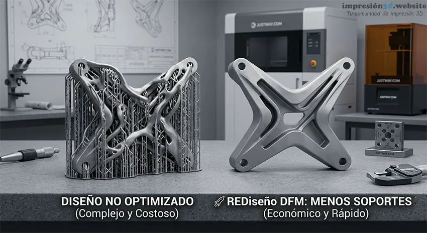
In industrial 3D printing, the material that becomes support structures costs exactly the same as the material that makes up your part. Furthermore, removing those supports requires skilled labor and post-processing time, which increases the cost of the quote. Designing to minimize or eliminate these structures is one of the fastest ways to reduce the cost of your project.
Workpiece Orientation and the 45-Degree Rule
In technologies that deposit or cure material layer by layer using support structures (such as Industrial FDM and SLA), steep overhangs require support pillars to prevent collapse. The rule of thumb in design for additive manufacturing is to avoid angles less than 45 degrees with regard to the construction platform.
If you redesign the overhangs as chamfers, ramps, or self-supporting arches in your CAD software, the machine will be able to print the geometry by resting on the previous layer. This eliminates the need for additional supports, reduces material waste, and ensures a much cleaner surface finish, free of the rough marks left by supports when they are removed.
Smart Guidance in Powder-Based Technologies (SLS)
Selective Laser Sintering (SLS) has a huge advantage: it does not use mechanical supports, since the unsintered powder surrounding the parts acts as a support bed. However, this does not mean that the geometry is unrestricted.
For online manufacturing services that use SLS, the cost is largely determined by the space the part occupies inside the print chamber (which is known as nesting or packaging). A part with a very extensive or complex design will occupy a large virtual volume, preventing the supplier from including other components in the same production run. Designing compact or modular parts that can be snap-fit together allows for optimization of chamber space, drastically reducing the unit cost when quoting.
3. Countersinking of parts and escape holes
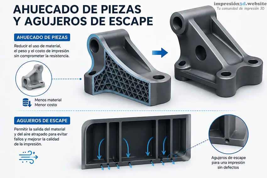
Printing a solid block of plastic or resin in an industrial setting is a quick way to blow your project budget. Smart hollowing of models is a fundamental DFM technique that reduces both raw material consumption and laser scanning time.
Why Is Printing Solid Parts a Financial Mistake?
Unlike desktop FDM printers, where the slicing software generates an automatic internal infill (such as the typical 20% honeycomb pattern), many industrial technologies, such as Stereolithography (SLA), assume that closed volumes in the CAD file must be 100% solid.
If you design a thick part without first hollowing it out in your modeling software, the machine will cure or fuse the entire interior. This not only drives up the cost of the printed material, but also causes internal residual heat to build up, which can lead to thermal stresses, cracks, or structural deformations on the part’s surface.
The Importance of Drainage Channels
Hollowing out a model in your CAD software (leaving, for example, a uniform wall thickness of 2 mm to 3 mm) is only half the job. If the volume is completely enclosed, the excess material will be trapped inside. In SLA, this means trapped liquid resin; in SLS, it means compacted powder. The algorithms used by online quoting platforms will detect this trapped volume and charge you for the part as if it were solid, since that material cannot be recovered.
To prevent this, you must include vent holes or drainage channels strategically placed in the less visible areas of the piece:
- Quantity and size: It is recommended to design at least two holes (one for the air or cleaning fluid to enter and another for the material to exit). The ideal minimum diameter is 3 mm to 5 mm.
- Location: They should be placed in the lowest or deepest areas of the internal cavity, depending on the impression orientation, ensuring that the material can drain by gravity during post-processing.
4. Design of assemblies and integrated moving parts
One of the greatest advantages of industrial 3D printing is the ability to manufacture complex, pre-assembled mechanisms in a single operation, a concept known as Print-in-Place. This eliminates the time and costs associated with manually assembling individual components, but requires millimeter-level precision in the CAD environment.
Clearance Tolerances for Mechanisms (Print-in-Place)
In order for a bearing, hinge, or gear printed as a single piece to move freely when it comes out of the machine, it is necessary to design a gap between the contacting surfaces. If this gap (or clearance tolerance) is too narrow, the layers will fuse together due to the laser’s thermal radiation or light scattering, turning your mechanism into a rigid, unusable block.
The ideal clearance depends directly on the technology selected for the manufacturing platform:
- Selective Laser Sintering (SLS): When working with powder, sufficient space is needed so that unsintered nylon particles can easily be dislodged from inside the mechanism. A minimum clearance of 0.3 mm to 0.5 mm between the movable walls.
- Stereolithography (SLA): Because of the high precision of the UV laser on the liquid resin, it is possible to achieve finer adjustments. However, to prevent the liquid’s capillarity from causing the parts to stick together before washing, it is recommended to maintain a gap of 0.2 mm to 0.3 mm.
- Industrial FDM: When extruding a viscous filament at high temperatures, the material tends to expand slightly to the sides. To prevent components from melting together, the safety distance must be at least 0.4 mm to 0.6 mm.
By adhering to these margins in your digital design, you ensure that the platform’s automated system will validate the file without any issues, guaranteeing optimal performance right from the start.
5. How the choice of process affects the online budget
Once you've applied the design rules to your CAD file, the final step in optimizing costs takes place directly within the on-demand manufacturing platform's interface. Global services such as Justway.com They use advanced instant-quote algorithms that analyze your model's geometry in seconds.
Learning how to work with the software's settings is just as important as the design itself.
The Impact of Technology on Automatic Quoting
Online quoting engines calculate the price based on the part's volume, the space it occupies, and machine time. Therefore, choosing the right technology for the design you've just optimized can drastically alter the final quote:
- SLA vs. SLS: If you designed a part with very complex geometries and were able to remove the internal supports by hollowing it out, SLS (Powder Sintering) It's usually the most cost-effective option for production runs, since optimized packaging lowers the cost per batch. If you're looking for a smooth, attractive finish and aren't too concerned about the amount of external support, SLA (Resin) She'll be your ally.
- Industrial FDM for high-volume prototyping: For large-scale enclosures where you've used thin walls and reinforcement ribs, professional-grade FDM with engineering plastics offers the most competitive cost per cubic centimeter on the market.
Optimization of Finishes and Post-Processing
Online platforms offer a wide range of surface finishes, from «as-machined» (as-printed) through to mirror-finish polishing, including sandblasting and chemical staining.
Each additional post-processing step requires human intervention and shop time. If your part is an internal component or a functional mechanical prototype, select the standard factory finish This will keep costs to a minimum. Reserve complex surface treatments exclusively for the final parts that face the user, where the aesthetic value justifies the extra investment.
Have you already optimized your parts and want to reduce manufacturing costs? JUSTWAY.COM is your best option
If you've already applied DFM rules, reduced wall thicknesses, and eliminated unnecessary supports, the next logical step is to test your design in the real world without overspending.
In Justway.com They combine state-of-the-art industrial 3D printing technology with an artificial intelligence engine that analyzes your file in seconds. Their on-demand manufacturing platform is specifically designed to streamline product development through key services:
- Instant AI-powered quote: Forget about waiting days for a quote. When you upload your CAD file (in formats such as STEP, IGES, or STL), the algorithm evaluates the geometry in real time, calculates the exact cost, and detects potential manufacturing errors before you spend a single penny.
- Comprehensive technology ecosystem: From high-resolution aesthetic prototypes in Stereolithography (SLA) and durable mechanical parts in Selective Laser Sintering (SLS), including functional components in Industrial FDM and final parts in metal 3D printing.
- Scalability: Their rapid prototyping service allows you to order anything from a single part for shape and fit validation to short- and medium-run production runs with guaranteed industrial repeatability.
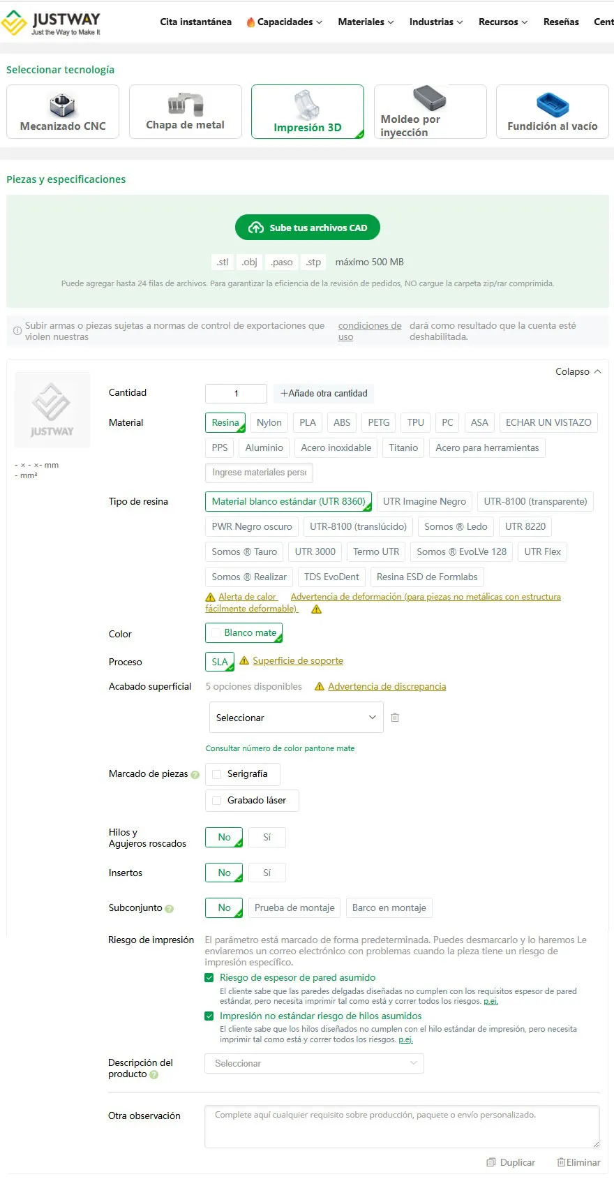
Step-by-step guide to the platform: As you can see on the Justway.com interface, the process is completely intuitive. Simply drag and drop the model, select the material (such as photopolymer resins, nylon, or engineering plastics), and configure the surface finish to get a transparent breakdown of the final price and estimated delivery times.
Don't let a great design get stuck on a hard drive: upload your CAD files to Justway.com just today, and I discovered how easy it is to produce on a professional scale with competitive factory prices and global shipping.
Conclusion: Designing with Production in Mind
Optimizing a CAD file for industrial additive manufacturing isn’t about limiting your creativity, but rather about aligning your ideas with the laws of physics and the economics of professional machines. Small adjustments to wall thickness, the inclusion of vent channels in hollow parts, or adherence to mechanical clearances make the difference between a costly project and a financially viable one.
By applying these DFM principles, you prepare your models to take full advantage of on-demand manufacturing platforms such as Justway.com. Its instant quoting systems and artificial intelligence immediately detect these geometric improvements, translating your smart design into a direct reduction in the final price and much faster turnaround times. True engineering design doesn't just aim to make the part work on screen; it also ensures that it is efficient and cost-effective when it becomes a reality.
Want to take your printing to the next level? Sign up at impresion3d.website/
If you're passionate about 3D printing, design, and technology, you can't miss out. Join for free at impresion3d.website/ and join the largest digital fabrication community in Spanish.
Don't get left behind! Sign up today at impresion3d.website/ to become part of our community.


Responses